
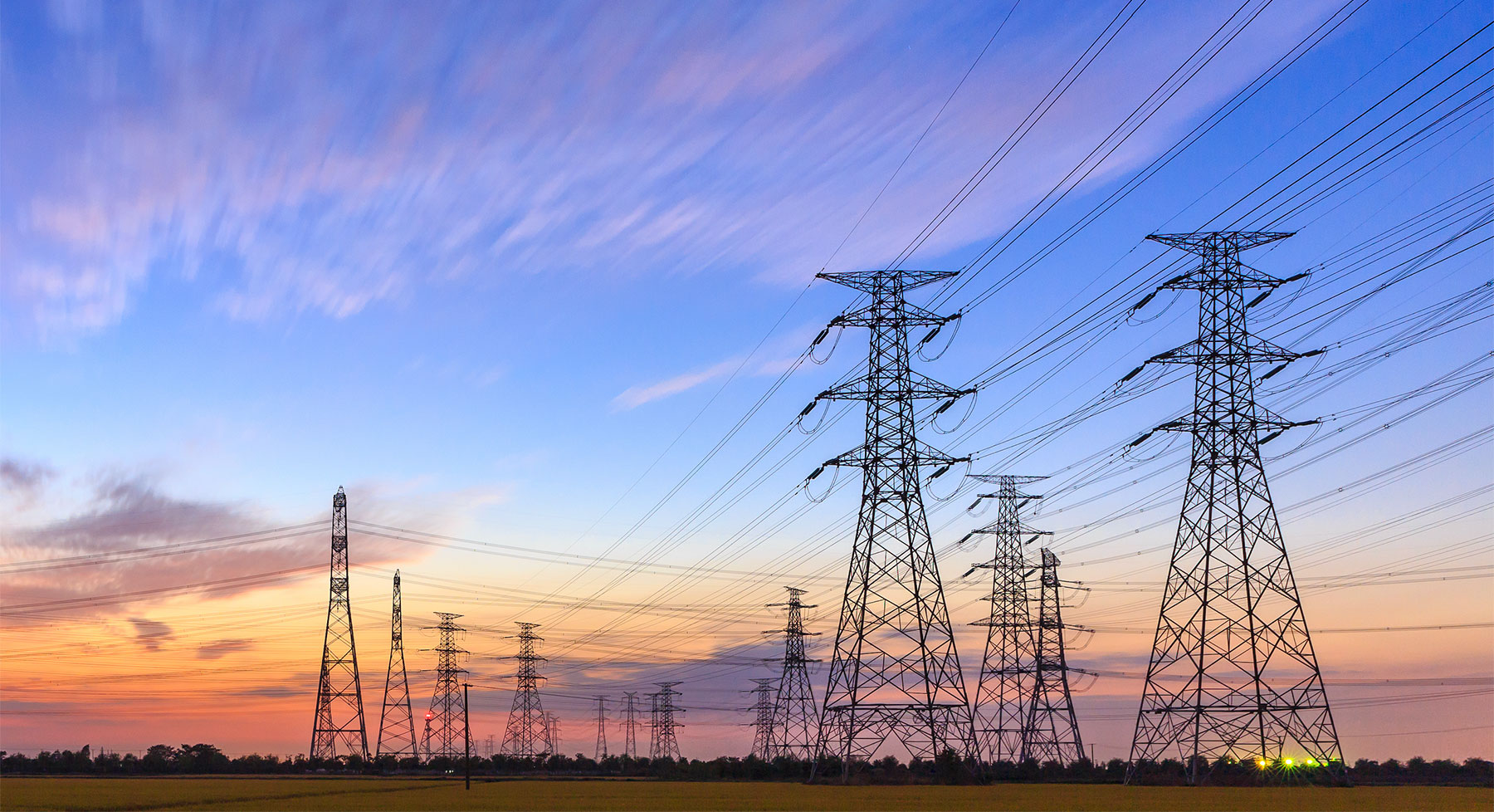

Constructing Power Transmission Towers: A Step-by-Step Guide
Building a transmission tower is a complex and meticulous process that requires careful planning, precise execution, and adherence to safety standards. As a leading manufacturer of power transmission towers, we understand the importance of providing valuable insights into the construction process. In this article, we’ll take you through the essential steps involved in building a transmission tower.
Site Survey and Preparation:
Before construction begins, a thorough site survey is conducted to assess factors such as terrain, soil conditions, environmental considerations, and proximity to existing infrastructure. The site is cleared of any obstructions, and access roads are constructed to facilitate transportation of materials and equipment.
Construction of Tower Parts:
Lattice Sections:
Lattice sections are the main structural components of lattice transmission towers.
Construction typically involves cutting steel rods or angles to specified lengths and welding them together to form the lattice structure.
Precision is crucial to ensure that the lattice sections meet dimensional tolerances and structural requirements.
Crossarms:
Crossarms provide support for power conductors and are mounted horizontally on the tower structure.
Construction involves cutting steel channels or angles to specified lengths and welding them to form the crossarm shape.
Mounting holes or brackets are added to facilitate attachment to the tower structure.
Braces and Diagonals:
Braces and diagonals provide additional structural reinforcement to lattice transmission towers.
Construction involves cutting steel rods or angles to specified lengths and welding them to form diagonal or angular braces.
Braces are welded to the lattice sections at designated connection points to enhance stability and load-bearing capacity.
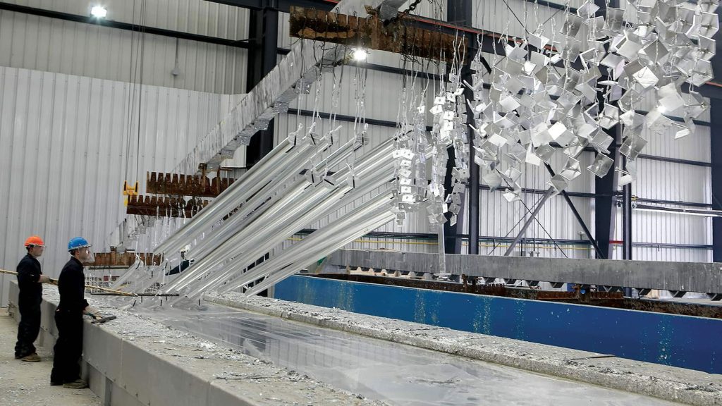
Hardware and Accessories:
Various hardware components, such as bolts, nuts, washers, and insulator strings, are essential for assembling and installing transmission towers.
Hardware is manufactured using high-quality materials and undergoes rigorous testing to ensure durability and performance in demanding environments.
Drawing Steps for Tower Parts:
Design Specifications:
The drawing process begins with gathering design specifications, including tower height, configuration, loading conditions, and material requirements.
Engineers use these specifications to create detailed drawings that meet structural, electrical, and regulatory standards.
![]()
Conceptual Design:
Engineers develop conceptual sketches or digital models of tower parts using computer-aided design (CAD) software.
Conceptual designs are reviewed and refined to ensure that they meet functional requirements and aesthetic considerations.
Detailed Drawings:
Detailed drawings are created for each tower part, specifying dimensions, material specifications, welding details, and assembly instructions.
Drawing annotations, symbols, and callouts provide clear and concise information for fabricators and assemblers.
Fabrication Drawings:
Fabrication drawings include additional details such as cutting dimensions, welding symbols, and surface finishes required for manufacturing.
Fabrication drawings serve as blueprints for producing tower parts in manufacturing facilities.
Assembly Drawings:
Assembly drawings illustrate how individual tower parts are assembled to form the complete tower structure.
Assembly instructions, bolt torque specifications, and weldment details are provided to ensure proper alignment and fitment during construction.
Quality Control and Inspection:
Quality control measures are implemented throughout the drawing process to verify accuracy, completeness, and compliance with design standards.
Drawing revisions and updates may be necessary based on feedback from quality control inspections and engineering reviews.
By meticulously designing and drawing tower parts, manufacturers ensure that transmission towers meet stringent quality and performance standards, contributing to the reliability and safety of power transmission infrastructure.
Foundation Installation:
The foundation serves as the anchor for the transmission tower, providing stability and support against various forces, including wind and seismic loads. Depending on the soil conditions and tower design, foundations may be constructed using techniques such as drilled shafts, spread footings, or mat foundations. Reinforcement bars are placed, and concrete is poured to form the foundation base.
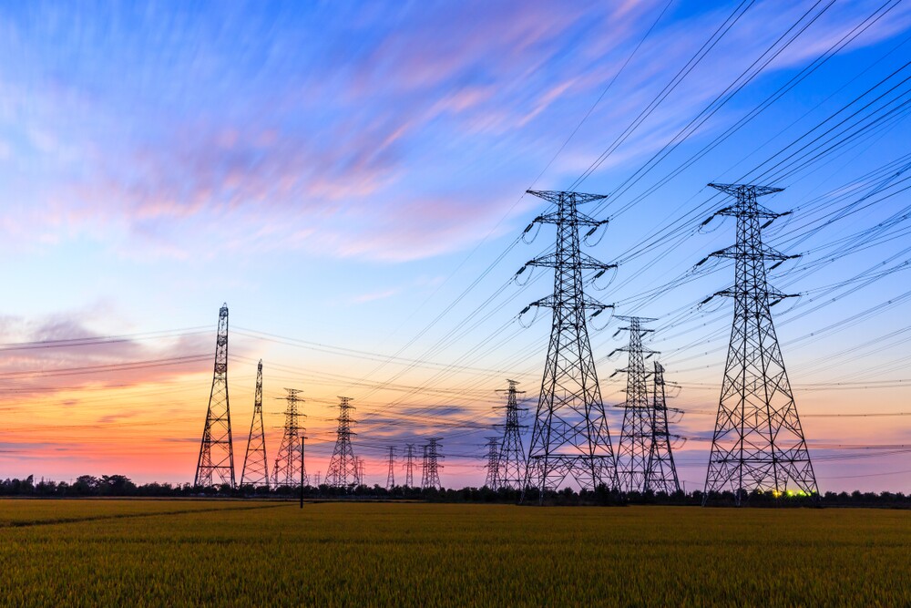
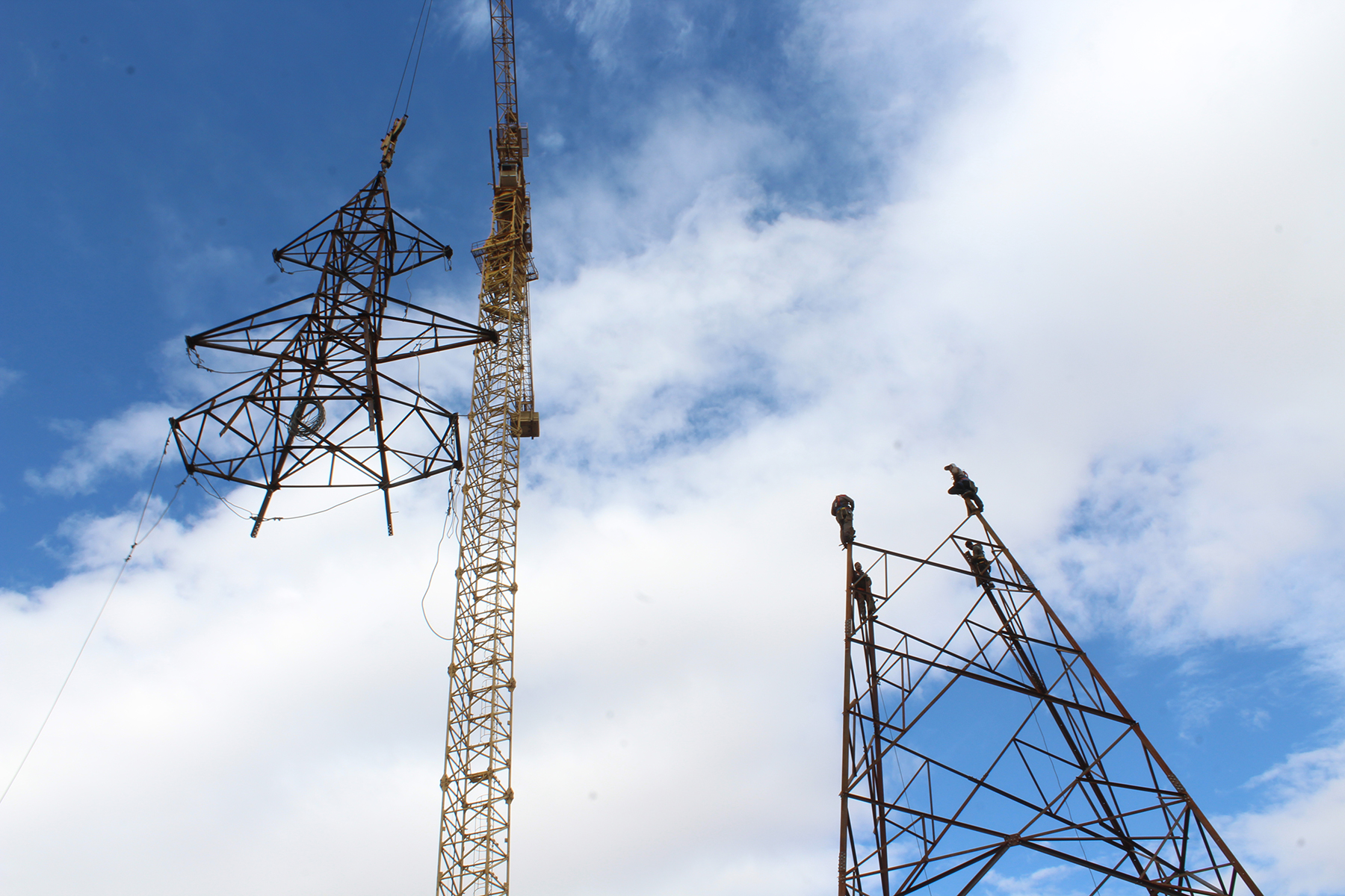
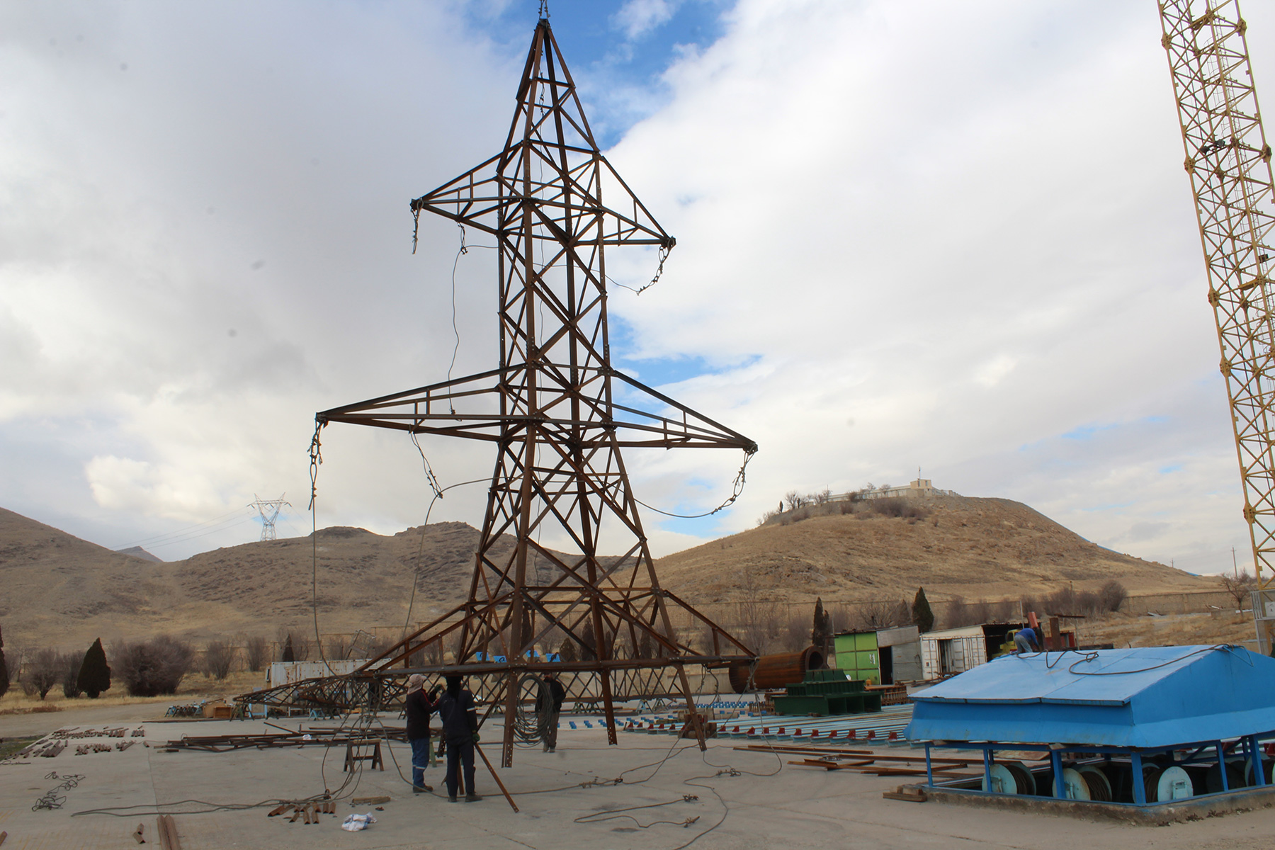
Tower Erection:
Once the foundation has cured sufficiently, tower erection can begin. Tower sections, which are prefabricated in our manufacturing facility to precise specifications, are transported to the site and assembled using specialized equipment such as cranes or helicopters. Each tower section is carefully lifted into position and bolted or welded to adjacent sections, ensuring structural integrity and alignment.
Installation of Crossarms and Insulators:
With the main tower structure in place, crossarms are attached to support the power lines. Insulators, which are essential for isolating the power lines from the tower structure and maintaining electrical insulation, are installed on the crossarms. Proper placement and configuration of insulators are critical to ensuring the safe and reliable operation of the transmission line.
Stringing of Conductors:
Conductors, which carry electrical current from the power generation source to distribution points, are strung between the towers using specialized equipment such as tensioning machines or helicopters. Careful attention is paid to tensioning and sagging of the conductors to ensure optimal performance and reliability under varying load conditions.
Grounding and Lightning Protection:
Grounding systems are installed to dissipate electrical surges and provide a path for fault currents to safely discharge into the ground. Lightning protection measures, such as lightning rods and surge arresters, are also incorporated to mitigate the risk of damage from lightning strikes, ensuring the safety and longevity of the transmission tower.
Final Inspection and Testing:
Once construction is complete, a final inspection is conducted to verify compliance with design specifications, safety standards, and regulatory requirements. Structural integrity, electrical insulation, and grounding systems are thoroughly tested to ensure reliability and performance under normal and adverse conditions.
In conclusion, building a transmission tower is a meticulously planned and executed process that requires expertise, precision, and attention to detail. By following these essential steps and adhering to industry best practices, we ensure the safe, reliable, and efficient operation of power transmission infrastructure, supporting the delivery of electricity to homes, businesses, and communities around the world.
References